Here's some more information on
my
LED
MATRIX

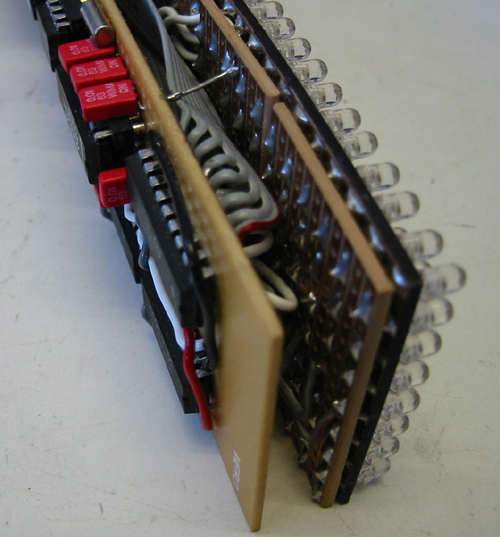
36x8 3mm Green leds. Using those complete 8x5 or 8x8 modules is like cheating...
;-)

The display consists of two parts, the LED/display board and the CPU/driver
board.
The two boards are stacked together with *lots* of short cables...

The CPU/driver board. Top row, left to right: 5 column drivers, intensity jumper,
powersupply, data connector.
Bottom left to right: ULN row driver, RS232 Levelshifter, RTC, Text EEProm,
Character EEProm,
PIC16F874, power connector.

Detail of the LED-module. See text for explanation.
Atlast I've built a working LED matrix project...
=)
It took some time but it was woth every minute!
LED Matrix Module
The module is built from two
VERO-boards that is mounted with the tracks in different directions. First the
leds was mounted on a black painted vero with the cathodes soldered to the
horisontal cu-tracks. Then the remaining anodes was threaded thru another
veroboard and soldered to the vertical tracks. This gives me a matrix with 8
cathodes and 36 anodes. Ofcource this isn't a good solution but as I like to use
vero-boards in the most extreme ways I thought I'll give it a
try...
CPU/Driver module
This module is quite simple. The
CPU clocks row-data thru 5 Serial-in-Parallell-out shift and store registers.
Then one of the rows is connected to ground by the ULN "driver" at the same time
the CPU sends a "strobe" to the SIPO registers. Then the
CPU sends data for the next row and so on. The data-stream to be shifted out is
built up by the CPU by looking up text data in one EEProm and then resolv
character/bit data in another EEProm. The EEProms (both text and chacterset) can
be updated from a PC thru the RS232 interface. The current time can be inserted in the textdata by inserting a "Ctrl+T"
character. Time is then read from a I2C RTC chip just before it is going to be
displayed. The software is written in MPLAB assembler.
More information will probably follow here some time in the
future...
>>>Thougths of
Enhancements<<<
Things I'll do when I get the time...
A
more simple solution for showing graphical images.
Temperature
sensor(s)
Software selectable LED intensity.
A nice enclosure.
A new
version with a doublesided PCB and SMD 2-color leds and IC's...
=)
Technical
information:
Microcontroller: PIC16F874
@20Mhz
Column Driver: 5x UCN5891A
Serial-Input-Parallell-Output shift and store register
Row
Driver: ULN2803A (8 bit Darlington driver)
Timekeeper:
PCF8583 I2C Clock/Calendar
Characterset Memory:
24C64 8k x8 I2C EEProm
Text-data Memory: 24C64 8k x8 I2C
EEProm
LEDs: 256pcs 3mm Green
Hi-Intensity
Serial Interface to PC: 9600-N-8-1 Full
access to both EEProms and RTC data
Power: 5-12v
@1A


