Nixieclock #1
Nixieclock #1 Schematic and Sourcecode availiable for donload now!
Please don't complain if you don't understand this or if something isn't complete. These are my blueprints...
NIXIE-CLOCK #1

Nixieclock #1
Nixieclock #1 Schematic
and Sourcecode availiable for donload
now!
Please don't complain if you don't understand this or if something isn't complete.
These are my blueprints...
I've always thought that those old nixie-indicator tubes are
really cool. Then one day I searched the web
for "nixie" and "schematic" to
see if someone still used those cool tubes. The first page that drew my
attention was http://www.electricstuff.co.uk/nixclock.html.
And guess what, He had a clock project!
And I like building clocks! =) By
the way, there was a gallery with other people who also had built
nixieclocks.
That page is really worth visiting!
So I searched for
someone selling nixietubes and found two nice guys. From the first guy I bought
10 quite
large Russian IN-18 tubes (0 to 9 indication) and from the other I bought 12
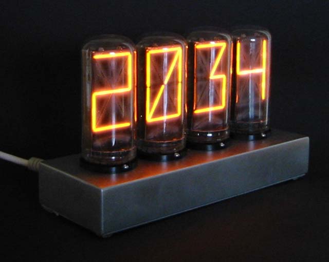
Really large Burroughs B7971
(15 segment)
As I wanted to make my own
design I designed two PCBs to the clock. One CPU-PCB and one
Drive-PCB.
CPU-PCB Contains a PIC 16F84, 10Mhz Crystal,
PCF8583 I2C Clock/Calendar, 7805, Rectifierbridge and
some passive
components. It has connections for all PIC ports. This board can be used very
general in many
of my uppcoming projects!
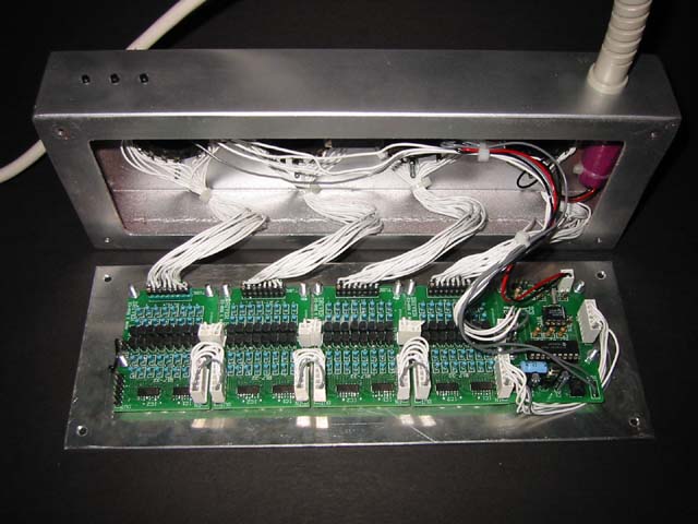
DRIVER-PCB Each
driver pcb contains two 4094 "8 stage shift-and-store bus register" and 16
MPSA-42
transistors with base and collector resistors (a total of 32
resistors)
These pcbs can also be used quite generally to drive nixies, leds,
relays and so on. Then I use as many
as I need to get the suitable number of
outputs. In this nixieclock I use 4 of them to drive all 60 segments.
As
I don't like to soil with etch-chemicals I had a company manufacture the pcbs
for me. Now I have pcbs
to this clock and for my future needs. Realy nice
pcbs and not that expensive. http://www.elprint.no/
At the moment there are no schematic och sourcecode availiable.
The Case was made of a length of 100x40mm steel
profile. As I wanted to welded plates to the ends of the
profile I had to
learn how to TIG-weld. I think I made a fairly good result for beeing a novice
in welding.
I drilled four holes for the tube-sockets, three holes for the
set, + and - buttons and one for the powercord.
The big hole in the bottom
was milled (I just *HAD* to try the milling machine)
The case was then
spraypainted with "crome-paint". As one could expect, it doesnt look like crome
at all!
On my next clock I'll send the case away for a real
crome-coating.
As the tubes can display letters as well as numbers, I added
a small greeting wich is displayed
every time the clock is turned on. 

Here's the
inside of the clock. Left picture is showing four driver-pcbs and one cpu-pcb
linked together and
mounted on the bottomplate. On the right pictude you can
see a small vero-type pcb with a transformer for the
logic power, a
fuseholder and a rectifierbridge for the 300v power to the nixies. The lilac
cylinder on the right
side inside the case is the backup-battery for the
timekeeper IC.
NIXIE-CLOCK #2

Nixieclock #2 in a case made from birch-plywood.

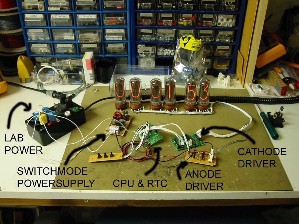
As you can see I'm using 6 Russian IN18 tubes.
The circuit is very much similar to #1 but this clock uses multiplex-drive for
the tubes.
I use the same design for the CPU and the cathode driver PCBs.
The anode driver module is built on VERO-board. Quick'n'dirty...
This clock is powered from +9v DC using the circuit from "Mike's
electric stuff"
Nixieclock #2 Schematic
and Sourcecode availiable for donload
now!
Please don't complain if you don't understand this or if something isn't complete.
These are my blueprints...
NIXIE-CLOCK #3


This is Nixieclock #3 in the dark. It has "stripe"
of blue leds giving the clock a "Hi-LoTech" look.
At the moment the blue
stripe is flashing on/off every second but I'll make it fade on and off
later...
The tubes are NL-841 by National Electronics found in an old
multimeter.

Here's the "guts" of #3... In the base to the left you can
see my standard Pic16F84 pcb
and a small Vero-board with a mainstransformer for the +5v. (The hi-voltage
for the tubes is taken
directly from the mains) To the right you can see the tube assembly with two
of my standard
cathodedrive-boards. The tubes are still in their original sockets and on the
multimeter PCB which
was cut down in size just to contain the tubesockets. Both the driver- and the
tubepcbs are mounted
on a small sheet of plexiglass. In this sheet there are 6 holes drilled, each
with a blue led.
This makes the sheet glow really nice blue at the ends... The plastic then goes
between the base
and the lid of the standard electronic-box that the clock is mouted in.
Probably I won't publish the schematic and sourcecode for this clock, Its very
much based on my
other two clocks, read about them above instead...
More clocks coming soon... I have 8 tiny tubes from an
old counter that I'll use for my next clock!